

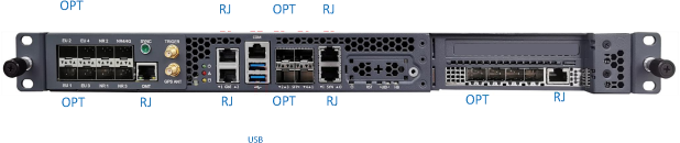
The LB9400 Baseband Unit (BBU) performs baseband signal processing and runs the protocol stack software to provide 4G/5G services. It also provides maintenance and monitoring functions for the extended small cell system.
The BBU uses a standard 19-inch, 1U rack-mount form factor and can be installed indoors or in a protected outdoor cabinet. Optical interfaces connect the baseband unit to extension units, supporting flexible distributed coverage deployments.
System Specifications
| Index Items | Index Value |
|---|---|
| Support frequency | NR N78 3300–3600 MHz |
| Duplex mode | 5G 5 ms single cycle (frame structure: DDDDDSUU); 2.5 ms single cycle (frame structure: DSUUU); 2.5 ms double cycle (frame structure: DDDDSUU) |
| Supported bandwidth | 5G 100 MHz / 100 MHz and other bandwidths |
| Maximum number of cells supported by a single BS | 5G: 3 (4T4R) |
| Number of online users supported by a single BS | 5G: 3 × 1200 |
| Number of active users supported by a single BS | 5G: 3 × 400 |
| Maximum number of EUs supported by a single BS | 4 |
| Maximum number of RUs supported by a single BS | 64 |
| EU cascade supported by a single base station | 2 levels |
Product Interfaces
| Port / Number | Slot | Identifier | Type | Description |
|---|---|---|---|---|
| OPT1–8 | 1 | EU / NR | SFP+ | 10G SFP+ optical ports for 5G fronthaul and extension unit connections. |
| RJ9 | 1 | Ethernet | RJ45 | 100/1000BASE-T adaptive Ethernet port for clock synchronization management and debugging, including delay compensation parameters. |
| — | — | GPS ANT | SMA-K | GPS antenna connection. |
| RJ10–11 | 0 | Ethernet | RJ45 | 100/1000BASE-T adaptive Ethernet ports for local BBU management and commissioning. |
| RJ12 | 0 | COM | RJ45 | Control port. |
| USB13–14 | 0 | USB | USB 3.0 | Local USB ports for a keyboard, mouse and USB flash drive during startup and commissioning. |
| OPT15–18 | 0 | SFP+ 1–4 | SFP+ | 10G SFP+ optical ports. Ports 15–16: fronthaul connections to the physical layer. Port 17: backhaul connection to IP-RAN or STN. Port 18: reserved. |
| RJ19–20 | 0 | SYN | RJ45 | 1PPS + TOD synchronization ports. Port 19: clock synchronization cascade output. Port 20: clock synchronization cascade input. |
| OPT21–24 | 2 | SFP+ 5–6 | SFP+ | 10G SFP+ ports for 4G fronthaul and extension unit connections. |
| RJ25 | 2 | COM | RJ45 | 100/1000BASE-T adaptive Ethernet port for local debugging of the 4G subsystem. |
Front Panel Indicators
| Indicator | Color | State | Meaning |
|---|---|---|---|
| Power | Green | Off | No power input or equipment failure. |
| Power | Green | Steady on | Power is supplied and the equipment operates normally. |
| Alert | Red | Off | Normal equipment operation. |
| Alert | Red | Steady on | BIOS failure or a sensor reading exceeds its threshold. |
| HDD | Yellow | Off | No SATA storage read activity. |
| HDD | Yellow | Flashing | SATA storage read activity in progress. |
Hardware Specifications
| Parameter | Specification |
|---|---|
| Working voltage | AC 100–240 V, 50/60 Hz; DC 36–72 V, 17–9 A |
| Maximum power consumption | < 300 W |
| Operating temperature | −5°C to +55°C |
| Operating humidity | 10%–85% RH |
| Storage temperature | −40°C to +70°C |
| Storage humidity | 5%–90% RH |
| Synchronization | GPS / BeiDou / 1588 |